Adjustable Aluminium Cross Beam - 1t to 3t up to 5 metres span - Lifting Beams & Spreader Beams - Lifting, Hoisting and Winching
Adjustable Aluminium Cross Beam - 1t to 3t up to 5 metres span
Key Features
- With 2 laterally adjustable snap safety load hooks, rotatable through 360° under load.
- With Cross Beam suspension for crane hook.
- Quick-snap system on top of the load hooks permits fast setting and adjustment of the load hooks using the grid dimension of 50 mm.
- All parts are made of aluminium or very high-quality plastics (except for bolts and suspension hooks).
Delivery Information
Order online for delivery to Mainland UK VAT eligible locations only. Delivery charges will be shown in the shopping cart. Despatch dates for products can vary, if urgent, please contact us. Request a quote for postcodes DD, IV, KW, PA, AB, BT, HS, TR. PO30-PO42, southern Ireland, Channel Islands. For international destinations restrictions may apply.
Returns Policy
Simply email us at sales@dale-lifting.co.uk or call 0161 223 1990 and we will be able to give you a returns authorisation code, which must be sent with the returned item. Returns should be authorised within 14 days from the day of delivery to you. Items should be returned in unused condition & due to the nature of our products a restocking fee may apply. Unfortunately, delivery charges are not refundable. Items returned without an authorisation code may not be accepted. Normally All refunds will be processed within 7- 10 working days on receipt of returned goods.
Non-standard (Quote only, pre-order or custom-made products)
Custom made to order products are not covered by our returns policy. Please ensure when ordering all measurements and capacities are correct as we are unable to refund on these products.
For more information see https://www.dlhonline.co.uk/terms-conditions
ALUMINIUM ;Adjustable Lifting Beam Applications - See full dimensions below
Lifting of various loads up to 3 tonnes in spans from 2 to 5 metres
Description:
- Adjustable aluminium mono-beam spreader
- Adjustment of hooks by removable pins (adjustable spreader beams only)
- Equipped with 2 articulated, rotating hooks with forged safety latches
- Tear-resistant eyelets for use with synthetic slings, cables, etc. Safety factor: 4
- No structural weld
- Manufactured according to standard NF EN 13155
- Group = FEM5
- Adjustment Pitch = 100mm
- Maximum hoisting speed = 16m/min
- Delivered with user’s and maintenance manual and EC certificate of compliance
- For superior capacities, contact us.
See important information for correct loading
Technical Specifications
| Part No. | Load Capacity (kg) |
Working Width (mm) |
Height (mm) |
Total Height (mm) |
Weight (kg) |
|---|---|---|---|---|---|
| 521020 | 1000 | 420-2000 | 570 | 630 | 45 |
| 531030 | 1000 | 420-3000 | 570 | 630 | 58 |
| 521040 | 1000 | 420-4000 | 570 | 630 | 71 |
| 521050 | 1000 | 420-5000 | 570 | 630 | 84 |
| 522020 | 2000 | 420-2000 | 570 | 630 | 45 |
| 522030 | 2000 | 420-3000 | 570 | 630 | 58 |
| 522040 | 2000 | 420-4000 | 570 | 630 | 71 |
| 523020 | 3000 | 420-2000 | 570 | 630 | 45 |
| 523030 | 3000 | 420-3000 | 570 | 630 | 58 |
Equipped with 2 articulated, rotating hooks with forged safety latches
Important Information
Install necessary accessories on the lifting beam ensuring that these accessories meet all the lifting beam use conditions
Attach the lifting beam to the lifting means
Adjust both lower points -taking the load geometry into account- sliding them onto the profile. Securely position the adjustable attachment points between appropriate steel locking components.
Hang the load on the lifting beam and perform lifting.
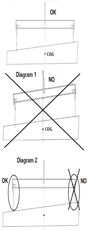
Ensure that the load is evenly balanced: the lifting beam must be horizontal during lifting (see Diagram 1) and efforts on axle direction of lower points vertical (see Diagram 2).
COG = Centre of gavity of the load
Otherwise, stop the lifting and correctly position the load, the lifting beam and accessories.
Choice of accessories
Accessories like shackles, hooks, slings, etc. must be adapted to all lifting operations.
For adjustable lifting beams, the following example is the most critical:
Important instructions
- Do not use for personnel lifting.
- Strictly forbidden to either be under or walk under the load
- Working temperature: -20° to +100°C.
- Accessories must be adapted to all lifting operation conditions.
- For all lifting operations, make sure that the load itself can withstand the bending stresses and deformations it is likely to be subjected to during the lifting operation.
- Never lift loads which have non-attached charges on top.
- Never exceed Working Load Limit of the equipment (W.L.L. – see engraving).
- The weight of the lifting beam, added to the weight of the load lifted, must be less than the capacity of the lifting appliance.
- Never mount more than one element in the hole of each lower point of the lifting beam.


